
For more information about what’s covered in this topic, download the NASH / NECA brochure Cable Management Steel Framing in the resource section.
Modern LGS frames are supplied with pre-punched holes in appropriate locations and of sufficient quantity to cover the majority of requirements for electrical and plumbing routing. Typically, service holes are provided in each top plate, noggin and stud. Common service holes range from 28-34 mm diameter and these are generally aligned between adjacent frame members.
The more service holes placed in the frame during manufacture, the fewer holes need to be made by installation contractors on-site and the less likely that such extra holes will be poorly made. Where congestion occurs, such as in wet areas and kitchens, or where specific routing is required, additional site-cut service holes may be needed.
Service hole diameter and spacing, whether factory-applied or made on-site, are required to meet NASH residential and low-rise steel framing design standards.
Typical electrical services for which holes may be required in webs are:
- Electrical cabling (especially switchboard access)
- Wired voice and data services (e.g. phone, ethernet)
- Broadband cabling/optical fibre
- Antenna/satellite dish cabling
Service holes are used for both electrical and plumbing services and consideration needs to be given to number, location and size, preferably during the detailing stage.
As LGS frames vary between fabricators, electrical trades should communicate with builders on the frame systems they are working with, to understand what service hole options can be provided. Depending on the frame design, the pre-punched service holes may be punched and flared (90 degrees or greater no need for cable grommets) or if not flared, site-installed grommets, as shown below, are required to be placed in the holes. If additional holes are made on-site then these will require grommets to provide cable protection.
It is important to match the grommet size to the frame manufacturer’s pre-punched hole sizes provided. As a guide, a house may require an average of 700 grommets.
Example of pre-punched, flared hole (below):

Example of punched hole with site applied grommet (below):


When providing input to your frame fabricator on service hole requirements, such as location and arrangement for wall studs, floor joists and bearers, the following should be considered:
- Predictability/convenience of hole locations for after trades and future services.
- Proximity of different services; regulatory, functional and practical considerations.
- Most common industry size for unflared holes is 28 mm for which plumbing and electrical grommets are readily available.
- Grommets assist plumbing and electrical trade work by protecting cables, preventing metallic contact between pipes and framing.
The figures below are taken from the NASH handbook ‘Design of Residential and Low-rise Steel Framing’:
- Figures 1 and 2 show a recommended maximum density of holes, without reference to the manufacturer.
- Figure 3 shows a typical stud hole layout.
- Figure 4 shows suggested floor beam penetration details, and placement of service holes in LGS C section joists showing hole position and diameter relative to section depth, while meeting design standards
Figures 1 and 2 Recommended maximum density of holes, without reference to the manufacturer.
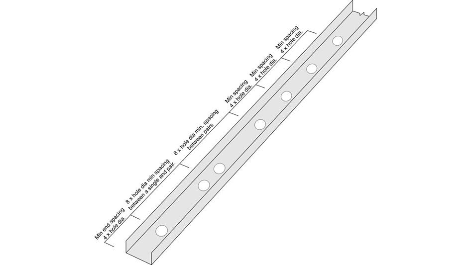

Figure 3 Typical Stud Hole Layout

Figure 4 Suggested floor beam penetration details, and placement of service holes in LGS C section joists showing hole position and diameter relative to section depth, while meeting design standards

For wall top plates and solid noggins, generally, a minimum of one hole is placed midway between adjacent studs. Where additional holes are required, site holes may be easily made using a manual or hydraulic punch, stepped/cone drill bit or metal cut hole saw.
Notes:
- Holes with spacing less than 4 hole diameters are deemed a pair.
- Holes with spacing less than 1.5 hole diameters may be joined to form a single elongated hole. This hole is still deemed to be a pair.
- Hole placement should not deviate greater than D/10 from centre line of stud
- Holes in studs to be no greater in diameter size than engineered pre-punched holes or as per NASH Part 2 sizing chart Table 3.1. If larger is needed seek engineers approval.
- Holes should not be placed in the flanges of steel members without reference to the frame manufacturer or engineer.
Resources

Download PDF
This guide contains information to help you meet your obligation to comply with AS/NZS 3000 when working on steel framing buildings

Available for Purchase
This Handbook supports the NASH Standard – Residential and Low-rise Steel Framing, Part 1: Design Criteria. It covers the structural design of floor, wall, roof and bracing systems as well as assisting with the design of connections, testing structures, durability, fabrication and construction practices. Design tables and manufacturers testing data are included for connections.

Visit Website
Standards Australia website - Wiring Rules: AS/NZS 3000:2018, Electrical installations, known as the Wiring Rules, are the technical rules that help electricians design, construct and verify electrical installations.

Featured Topic
Tools and Accessories
In this topic, we look at tools required for making service holes.